
Showing posts with label graphite. Show all posts

Monday, August 29, 2011

What are the problems with LFTR technology?

What are the problems with MSR/LFTR technology? This turns out to be a hard question to answer. Since there are a large number of LFTR design options, however, it is difficult to identify a set of problems that shared all of the options. Rather we should talk about elective choices, and the problems that a MSR/LFTR designer would face if a certain option were chosen.

Protactinium would seemingly pose a problem for thorium breeding. The Protactinium nucleus is a very big target for neutrons in a LFTR core. Kirk Sorensen discussed the problems posed by Pa-233 and U-233 in MSR blanket salts:
From these cross-sections, you can see that thorium-232 has a moderate cross-section for absorption, but there’s so much of it in the blanket that it does almost all the neutron-absorbing (as we would want).

After absorbing a neutron, the Th-232 becomes Th-233, which has a monster absorption cross-section (almost 200x that of Th-232) but its half-life is so short (22 min) that it isn’t around very long to absorb a neutron.

Once it turns into Pa-233, the absorption cross-section is still over 5 times greater than the Th-232. That is one of the basic reasons why it’s so important to isolate the Pa-233 from the blanket–in order to prevent another neutron absorption. This is a key step that you just can’t do in a solid-core reactor that’s trying to “burn” thorium (and achieve a conversion ratio of > 1.0).

Finally, the Pa-233 decays to U-233 in 27 days. The U-233 has a huge cross-section, mostly for fission (531 barns) but with a lot of absorption (45 barns). Thus, uranium-233 left in the blanket will really want to gobble up blanket neutrons and cause fission. That leads to even more trouble, because that will deposit fission products in the blanket, complicating reprocessing and making the blanket “hot” with radiation from fission products.

All of these factors argue for getting protactinium of out the blanket and letting it decay to U-233 outside of the neutron flux. The U-233 can then be removed by fluorination to UF6 and adding it back to the core salt by reduction to UF4. Continuous refueling of the core means that excess reactivity in the core can be held to almost nothing, an extremely important consideration for safe operation that is very difficult to achieve in a solid-core reactor.
This problem would seem to be compounded in a single fluid LFTR, in which thorium breeding takes place in the same fluid that carries the fissionable nuclear fuel. protactinium is not easy to remove from molten salts. It turns out that it is a lot easier to wait until the Pa-233 is transformed by a gamma particle emission into U-233. There is, however, a proliferation related disadvantage to Protactinium separation in addition to the problem posed by the need to separate Protactinium out of its carrier salts. Dr Buzzo points out,
U-233 is perfectly suitable for use in a nuclear weapon, at least in theory. The thing which makes it difficult is that there would be some U-232 as well. This does not preclude the use in a weapon, but the short halflife of U-232 makes it much more radioactive and therefore difficult to handle. . . . .

it's really the U-232 which is going to make the uranium recovered less suited for weapons use.

However looking at the aspects of protactinium separation, I'm wondering if this could be a hole in the process which would allow for much lower U-232. U-232 is the daughter product of Pa-232 just as U-233 is the daugher of Pa-233. Pa-233 has a half-life of 26.9 days but Pa-232 is only 1.3 days.

This seems as if it could cause a problem. Basically if you separate the protactinium and let it decay for about eleven days, for example, you've gone through eight half-lives of Pa-232 but less one half of a halflife cycle of Pa-233. Thus you still retain about three quarters of the Pa-233 you started out with but the Pa-232 has been diminished to less than half a percent of what you started with. You could do it for even longer before you start to loose a lot of the Pa-233.

Thus, at this point you could do the process over again, removing the uranium and retaining the protactinium and you would have a very high concentration of Pa-233 and very little Pa-232, which is where the U-232 would come from. This is not very difficult and could easily be done with what is available. The result is basically an easy source of weapons grade U-233.
Therefore, according to Dr. Buzzo, it is undesirable to to separate Protactinium from its carrier salts, if you are worried about proliferation. In response to Dr. Buzzo's proliferation related concern, David LeBlanc commented,
Many of us on this site strongly favor the 2 Fluid design of having one salt with the U233 (and maybe a little thorium) and a separate salt for the thorium. The Single Fluid design however has been what most researchers have focused on since the late 1960s.

In a Single Fluid design it is much more difficult to try to skip Pa removal and still break even. The way to lower the neutron losses to Pa is to lower the average neutron flux it experiences (especially thermal neutrons). You can do this by simply having a much larger core or by having excess salt that you cycle in and out of the reactor loop. However, in a Single Fluid design, having more fuel salt means having much more fissile material to start. This is not a deal breaker but a serious impediment nonetheless.

In a 2 Fluid design we can lower losses to Pa down to almost nothing by simply increasing the volume of blanket salt. This means paying for more thorium and carrier salt but thorium is very inexpensive (the true potential cost of mass produced Flibe salt is unfortunately one of the big unknowns). For example, 1960s 2 Fluid designs had about 260 tonnes of thorium in the blanket salt versus about 70 tonnes in the later Single Fluid design.
In another thread, Dr. LeBlanc commented,
in a 2 fluid reactor you can have more blanket salt cycled in and out of your reactor to really lower the loses to Pa. Here are some numbers to give you an idea of losses (remember you can almost double the values since you often lose a second neutron to U234):

Single Fluid design with a 3 day Pa removal time, Pa losses are 0.0017 out of 2.23 neutrons

Single Fluid design WITHOUT Pa removal, Pa losses are 0.05 out of 2.23

2 Fluid design with lots of blanket salt, NO Pa removal (ORNL 1467) 0.0079 out of 2.22 (0.36%)

2 Fluid design with less blanket salt but Pa removal (ORNL 4528) 0.0002 out of 2.22.
The neutron losses for all designs noted by Dr. LeBlanc are acceptable for breeding purposes. Thus a LFTR designer has a number of potions to chose from, in creating a design that best meets breeding goals. As it turns out, according to Dr. LeBlanc, none of the options pose serious barriers to breeding goals, although one option - Single fluid design with no Pa removal - offers the most disadvantages.

There are a number of number of problems associated with core graphite in thermal MSRs. Graphite cores breeders offer huge scalability advantages, because they can be started with a small charge of fissionable material. It takes about 10 times more fissionable material to start a Fast Breeder reactor, than a graphite moderated thermal breeder requires. This makes an enormous difference in the number of reactors that can be started quickly. Well over a year ago I posted a comment on Brave New Climate,
By 2050 if not sooner, we will begin to need breeder technology in order to keep up with world energy demand. The question is which Generation IV technology will have the advantage. I have argued that LFTRs will, because they are far more scaleable, can be manufactured more rapidly, are more flexible, and will be perceived as safer, and less of a proliferation danger. (I am not arguing the last two are the case, I am now satisfied of IFR safety, and proliferation is an anti-nuclear canard,.) Claims of high IFR breeding ratios are not confirmed from IFR design plans. The only IFR designs I was able to locate on the Information Bridge, had a maximum breeding ration of 1 to 1.07, the same as 1970′s ORNL MSBR designs. Statements by IFR advocates indicate no higher breeding ration can be expected in the near term. Since as many as 12 LFTRs of equivalent power output can be started for every IFR, if the IFR has no breeding ratio improvement, it cannot be seen as the most likely LWR replacement. Never-the-less world wide we will see LMFBRs. I believe that the Indians are considering plans to build as many as 300 500 MW LMFBRs, and I fully expect Russia, China and Japan to enter the LMFBR race.

However, it turns out that the reactor grade plutonium from spent light water reactor fuel becomes a chocking point for Generation IV reactors. The world supply of unused reactor fuel now is sufficient to now start a very large number of LFTRs, but not of IFRs. Given that current IFRs designs have no breeding advantage over the LFTR, allotment of RGP to start LFTRs offers some enormous scale advantages. Given that LFTRs are likely to cost less to build, can be built more rapidly, and are likely to have less political and public opposition, it seems to me that IFR advocates are backing the wrong horse in the Generation IV breeder race.
Needless to say, IFR advocates were not pleased by this comment, but they have not been able to show that I was wrong. However, in order to wrap the thermal scalability LFTR advantage, we have to find ways to solve the graphite problems. The two major graphite problems, are
* graphite deterioration in a high neutron flux environment

* And a positive coefficient of reactivity associated with core graphite.
If we want to build a large number of LFTRs quickly then we have to find a workaround. On solution to the graphite deterioration problem is to replace the core graphite every few years. One way to accomplish this is by using graphite pebbles rather than a graphite core structure. The pebbles can be replaced as they reach a point where their deterioration become unacceptable. "Cyril R" points out,
Graphite pebbles have a lot of potential advantages. In one two fluid design, the pebbles are filled with blanket salt. This means every pebble is a barrier, and so barrier maintenance is potentially easier. However, circulating pebbles turns out to be a bit tricky, and with a lot of pebbles all containing liquid blanket salt, broken pebbles seem like a big risk in a true two fluid design. . . .

However, if solid graphite pebbles were to be used in a two fluid design like David's tube in shell, things would be easier. The pebbles wouldn't circulate, but act as fairly static moderator. The simple graphite pebbles would last longer and be easy to replace. Because pebbles have a high void fraction, the traditional MSR graphite density could not be achieved (probably at least half the graphite density).
Lars commented,
Graphite in the blanket would serve to slow the neutrons down. The slower spectrum will make all cross-sections larger so less blanket salt is required to absorb the neutrons. However, the cross-section of the fissile will grow dramatically faster than anything else - which is not good in the blanket. It means that we have to keep the u233/th232 ratio much lower to keep fission in the blanket rare. So one result is that we have to process the blanket faster to keep the u233 concentration down. I'm not sure how big an issue this is - the original 2-fluid ORNL designs were thermal and so they faced this issue and did not identify it as the reason to stop work on the 2-fluid design. But they also generally assumed they could process things at a pretty high rate.

Another effect of graphite in the blanket would be that any neutrons that hit the exterior wall would be slow so they are much easier to absorb and stop and are easier on that wall.

Another effect is that it becomes more cost effective to absorb a higher percentage of the neutrons in the blanket since the thorium in the salt is more effective at absorbing slower neutrons.

One BIG concern is that if there is a big break in the plumbing for the blanket salt you will drain the neutron absorber from the blanket. With the graphite present it will slow down and reflect many neutrons back toward the core. In normal operations the blanket salt will absorb most of them. With the blanket salt drained they will go back to the core. In other words, if you get a dramatic break in the blanket plumbing and drain the blanket salt the reactivity of the core will go up. This can not be allowed. The design would need to somehow guarantee that no matter what the reactivity of the core does not go up in any accident scenario.
David LeBlanc described his position.
your don't want graphite or other good neutron reflecting material in the blanket zone or you end up with reactivity problems if the blanket salt drains or even just gets hotter and less dense.

For the core, using graphite is always a serious option and pebbles certainly have some big advantages but they don`t really help with the core to blanket barrier issue. Even a core with graphite moderator you still need some sort of physical barrier to the separate the fuel and blanket salts (any Two Fluid or 1 and 1/2 Fluid needs barrier material). A graphite core of logs might make things a little easier because we could have a simple metal cladding wrapped around it that would need no structural strength of its own). My google tech talk also shows a method to use individual graphite logs bunched together as the barrier but too complicated to describe here.

So in general, pebbles versus logs is always going to be an interesting trade off of pros and cons. In terms of radiation damage, I still don`t know if anyone has a good idea of how long a pebble would be last. The expansion beyond original size is no longer of structural concern for the core (like it would be for logs) but it the pebble starts to crack due to expansion then we do have a big problem. ORNL seemed to be on the fence regarding this in their early studies with pebbles (which seemed always to be a Plan B that never got too deep a look).
In most cases, comments are or can be referenced back to ORNL MSR research. I could quote more of the graphite pebbles discussion which illuminates a number of problems, but this is enough to suggest that MSRs problems exist, but that solutions and work arounds are available. Each solution or work around may have its cost, so any MSR/LFTR design is going to offer a compromise. The question facing the LFTR designer is, which set of compromises works best given design goals. Because the graphite moderated LFTR is highly scalable even without a high breeding ratio, designing the LFTR to produce just one U-233 atom for every fissionable atom burned. Not only does this decrease proliferation risks, but it allows for more breeding ratio lowering compromises in the LFTR design.

There would be a set of problems for every MSR/LFTR design, but there appear to be an acceptable set of compromises for the problems we have looked at. At least some of the compromises I have reviewed, seem to have secondary benefits that are consistent with probable design goals. In the nearly 40,000 comments of the Energy from Thorium discussion section, no one single killer problem has yet popped up. This most likely means that development of various MSR designs including LFTRs will not involve serious development challenges, and we can be reasonably but not entirely certain that serious problems will not impede MSR/LFTR developmental progress.

Thus it can be asserted with reasonable certainty that the LFTR offers a potential long term solution to human energy needs, that is consistent with a high energy lifestyle, and which will not create the sort of safety, waste, proliferation and capitol cost problems associated with LWR power technology.

Thursday, August 18, 2011

DA Ryan and the Miraculous MSR Graphite Fire

And the angel of the LORD appeared unto him in a flame of fire out of the midst of a bush: and he looked, and, behold, the bush burned with fire, and the bush was not consumed. - Exodus 3:2
When I began my investigation of the graphite fire risks this spring, I had formed no fixed opinion about the supposed danger. I had, of course, run across numerous references to graphite fire risks, including a statement from the redoubtable Ed Lyman of the ever vigilant anti-nuclear Union of Concerned Scientists. Lyman tells us,
A second unresolved safety issue concerns the reactor’s graphite coolant and fuel pebbles. When exposed to air, graphite burns at a temperature of 400°C, and the reaction can become self-sustaining at 550°C—well below the typical operating temperature of the PBMR. Graphite also burns in the presence of water. Thus extraordinary measures would be needed to prevent air and water from entering the core. Yet according to one expert, “air ingress cannot be eliminated by design.”
Yet a statement from General Atomics, a business which has designed and built graphite core reactors claims,
Numerous tests and calculations have shown that it is virtually impossible to burn high-purity, nuclear-grade graphites. Graphite has been heated to white-hot temperatures (~1650°C) without incurring ignition or self-sustained combustion. After removing the heat source, the graphite cooled to room temperature. Unlike nuclear-grade graphite, charcoal and coal burn at rapid rates because:

* They contain high levels of impurities that catalyze the reaction.
* They are very porous, which provides a large internal surface area, resulting in more homogeneous oxidation.
* They generate volatile gases (e.g. methane), which react exothermically to increase temperatures.
* They form a porous ash, which allows oxygen to pass through, but reduces heat losses by conduction and radiation.
* They have lower thermal conductivity and specific heat than graphite.

In fact, because graphite is so resistant to oxidation, it has been identified as a fire extinguishing material for highly reactive metals.
Thus the issue of graphite fires is open to question, and should be most properly settled by scientific investigation. The New Scientist published a discussion of the General Atomic claim in its November 4. 1989 edition. The New Scientist came to a graphite does burn reluctantly, and is not very dangerous view, pointing to research by Peter Kroeger's of Brookhaven National Laboratory for support. I concluded my initial investigation of the graphite fire danger by noting
Needless to say, Ed Lyman forgot to mention any of Peter Kroeger's research, the General Atomic's argument, or other arguments that makes his simple "Graphite burns" statement less than a serious inditement of pebble bed reactor safety.

Even less so, does the "graphite burns" statement a serious safety objection to the use of graphite in the core of Molten Salt Reactors. It should be noted that the presence of liquid fluoride salts would be a serious inhibitor of any graphite fire, and in the event of salt drainage from a MSR core, a graphite fire would not be a safety issue, because both fission products and nuclear fuel would drain out of the core along with the coolant salt. Thus even if we reject the General Atomic's contention that Nuclear Graphite does not burn, the graphite burns objection does not appear to raise a serious concern about Molten Salt Reactor safety.
My conclusions were based on facts - Peter Kroeger's graphite research, and the application of logic to those facts. Anyone wishing to disagree with my conclusions should either argue that I misrepresented Kroeger's research, or Kroeger's research was seriously flawed, or that I committed logical errors in reaching my conclusions. So far no one has used any of these rational approaches to dispute my claims.

My discovery of Kroeger's research was not the end of the line as fare as my investigation of the graphite fire risk. I had two supposed reactor graphite fire risks to explain. The Windscape fire, and the Chernobyl fire.

DA Ryan asserts
CB (Charles Barton) seem unable to absorb any information that contradicts their position.
What information? Ryan presents no facts, no analysis of logic which contradicts my views. Ryan's evidence is not based on research. In facts Ryan ignores all nuclear graphite fire risk research.

When I pointed out to Ryan a recent statement on the Windscale fire by the UK Nuclear Safety Advisory Committee that,
Inspections have shown that there was NOT a graphite fire: damage to graphite, caused by severely overheated fuel assemblies, was localised.
Ryan remarked,
the paper you point to with regard to Winscape is the minutes of a committiee meeting not an official statement or scientific anaylsis that has been subject to peer review. One could be unkind and describe it as “gossip”.
Yet the UK Nuclear Safety Advisory Committee reports the results of acrtual observations. None of the statements about the Windscape fire which Ryan refers to is based on evidence drawn from actual observation inside the core of the Windscape reactor. I went to the trouble of documenting several accounts of the Windscaple accident in0rder to show that the evidence in support of the UK Nuclear Safety Advisory Committee report has long been known, and that evidence includes photographs taken from inside the windscape reactor, and a link to a presentation by M.T. Cross, at the Brookhaven National Laboratory Graphite Research Reactor Workshop, May 9-10 2007. The presentation included numerous slides of photographs taken in the interior of the Windscape reactor that shows fuel capsules that were damaged or destroyed by fire, while the graphite structures that contain them are still intact. I wonder if Mr. Ryan would also categorize those photographs as "gossip."

If Mr. Ryan still can maintain his "Windscape was a graphite fire" position with a straight face, he must explain the miracle of the Windscape graphite, the graphite burned but was not consumed, just like Moses burning bush.

Mr. Ryan accuses me of ignoring the precaitionary principle, but he has managed to stumble very badly in his attempt to establish that there is a MSR core graphite fire risk. Ryan has posted a long response to my critique of his treatment of MSR technology, and to Bill Hannehan's critique. The first of Ryan's comments has to do with graphite fire. Ryan states:

Another critique of my critique of the LFTR can be found here:
http://nucleargreen.blogspot.com/2011/08/d-ryan-msrlftr-critique-not-ready-for.html
As with the previous ones they either deliberately missread my critique in an effort to build up stray man arguments or reading just isn’t one of Mr Bill Hannahan, or “Rank Amateur” (his words http://daryanenergyblog.wordpress.com/ca/#comment-126) Charles Barton’s stronger points. I’ll leave it to the reader to decide which.

Firstly, they misrepresent my views on graphite, which I point out is a “perceived fire risk” I was never suggesting it will catch fire if you put a match to it. I make this point repeatedly in the comments above, I even added a little section to chapter 6 to describe the two sides of the fire risk argument and clarify my position. But the fact opaque minds of BH and CB seem unable to absorb any information that contradicts their position. They also seem to have no idea about the concept of scientific uncertainty or the precautionary principle or the most basic concepts of how passive safety is guaranteed. These would require “some” action be taken on this issue. Indeed they compound there mistake by then misunderstanding why graphite is used in Class D fire extinguishers (for liquid metals!). Oh, and BH suggests you can use jet fuel to put out fires later on (yes really!). I’ll let the reader assess the practicalities of that!

Ryan starts off with a straw man argument, that is the suggestion that we were attributing to him the view that graphite

will catch fire if you put a match to it.

I never attributed that with to Ryan, and he, of course, can produce no quotes that say otherwise.

I do view Ryan's claims about about the fire risks posed by graphite cores in MSRs are at best exaggerations. Research on Graphite safety conducted in the United States after the Chernobyl nuclear accident, found that graphite was a safe material for nuclear cores, and that it posed little or no fire danger. I argued this because my own review of literature on graphite fire danger demonstrated that graphite posed no fire risks for Molten Salt Reactors. Mr. Ryan has not presented research evidence contradicting my conclusions.

Ryan attempts to discredit me by claiming that the word "perceived" in the phrase "perceived fire risk" some how invalidates our arguments against his position. In fact the word perceived has more than one meaning. It can be understood to mean, "detected by instinct or inference rather than by recognized perceptual cues," or it can mean, "detected by means of the senses." These two meanings are somewhat contradictory which makes the word "perceived"an excellent weasel word. Before we look further at what Mr. Ruan means when he uses the word "perceived," we ought first to look at what Ryan actually says about graphite and graphite fire risks. In his original essay, Ryan writes,

Another issue is that graphite core. As I detailed previously with regard to the HTGR (part 6.4.3) it’s a potential fire hazard. Thus we would need to put the MSR within a containment dome of sorts. Again, as with the HTGR, this dome need not be built to the same exacting standards of a LWR dome as we are merely trying to contain a graphite fire, not an out of control reactor.

The word perceived certainly does not decrease Mr. Ryan's certainty about the necessity of taking steps to control graphite fire risk. In addition to structural recommendations,

We would need an effective on plant fire control team and some form of fire detection and suppression system, within the containment dome and all the necessary gear that this entails. Again, I refer you the relevant section of the HTGR analysis, but needless to say such an arrangement would involve certain costs.
So Mr Ryan seems to mean by perceived fire risk, a plausible risk of graphite fire. But is there plausible risk of graphite fire in MSRs? Graphite fire research seems to show that there is none Ryan ignored that research when he made the graphite fire claims.

I argued that the evidence on graphite fire risks suggests that there are no circumstances in which the laws of nature would allow us to believe that a graphite core of a Molten Salt Reactor could catch on fire. If an idea contradicts the laws of nature, it is a misperception, a mistake, or a miracle. Mr. Ryan should have explained how the graphite core of a molten salt reactor could catch on fire despite the fact that a graphite fire in A MSR core would seemingly violate the laws of nature. Apparently Mr. Ryan's precautionary principle includes protecting the public from miracles.

Mr. Ryan fails to not the difference between assertion as rhetorical strategies, and actually demonstrating his case. Ryan acknowledges,

I could go thro this line by line but there’s no point, all they succeed in doing is demonstrating their own ignorance of the facts and inability to absorb any information that contradicts the LFTR gospel.

Ryan however, fails time after time to demonstrate that Bill and I are as ignorant as he says we are. He tells us that Bill is mistaken in asserting at low vapor pressure of MSRs is an advantage because,

The pressurization issue is a bit of red herring, the major materials stumbling block is the issue of the combination of corrosive attack under temperature, with a bit of radiation thrown in for good measure.

In this argument Ryan simply ignores ORNL finding from the MSRE. ORNL-TM-4171 (Postirradiation Examination of Materials from the Molten Salt Reactor Experiment ) reported that

The MoltenSalt Reactor Experiment operated very successfully. The fuel loop was above 500°C for 30,807 hr and contained fuel salt for 21,040 hr. A surveillance program was active during operation to follow the property changes of the graphite moderator and the INOR-8 structural material. After operation was discontinued in December 1969, several components were removed for examination. These included a graphite moderator element from the core, a control rod thimble, freeze valve 105, the sample cage and mist shield from the fuel salt pump bowl, a copper sampler capsule, tubes and a portion of the shell of the primary heat exchanger, and tubes and two thermocouple wells from the air-cooled radiator.
The overall findings were that
Examination of these materials showed excellent mutual chemical compatibility between the salts, graphite, and INOR-8. The INOR-8 exposed to fuel salt formed shallow intergranular cracks believed to be due to the ingress of the fission product tellurium. The INOR-8 was also embrittled by exposure to thermal neutrons, and this was attributed to the formation of helium by the (10)B(n,a)(7)Li transmutation.
The ORNL report found that
The primary corrosion mechanism in the fuel salt system was selective removal of chromium by 2UF4 + Cr(in alloy) Z+ 2UF3 + CrF& salt), and the concentration of chomium in salt samples was the primary indicator of corrosion. . . . The total increase in chromium in the 4700-kg charge of fuel salt is equivalent to leaching all of the chromium from the 852 ft2 of INOR-8 exposed to fuel salt to a depth of about 0.4 mil.

Since the coolant salt did not contain uranium, the corrosion rate was extremely low. During operation, the chromium content of the coolant salt remained at 32 ppm, within the accuracy of the analysis.
ORNL scientists went on to identify two solutions to the intergranular cracking problem, and proposed to solve the minor chromium corrosion problem by removing chromium from metal alloys. Mr. Ryan failed to examine the results of the ORNL experiment that was designed to determine the effects of
the combination of corrosive attack under temperature, with a bit of radiation thrown in for good measure.
Those findings were that there were some developmental problems, but none that were show stoppers.

One way to avoid mistakes due to ignorance in scientific matters is to pay careful attention to what scientists say in research related documents, and to quote them exactly and in context. This would be the approach that both Bill and I take, but Mr. Ryan does not seem to regard it as necessary to examine the actual research before he makes sweeping and all encompassing judgements on all sorts of matters. Thus his pronouncements on MSR related problems are invariably made without reference to ORNL research work product, which would be the primary source of information on MSR research.

Most of Mr. Ryan's response is an personal attack on Bill and I have left it to Bill has answer those criticisms.

Saturday, July 23, 2011

Recounting the Windscale Story

The Blog, Histories of Things to Come, includes a post titled Nuclear Leaks 8, Sellafield, aka Windscale. The Nuclear Leaks part of the post title is the give away that the blog is not exactly cheer leading for nuclear power, but there is a good deal to learn here. Most of the story is told through links to a BBC documentary on the Windscale reactor fire. The BBC narrative fingers politicians, in particular British Prime Minister Harold MacMillan as playing a major causal role in the Windscale fire, by pressuring Windscale leadership to go beyond what was safe in reactor operations.

The original Windscale reactors were modeled after the ORNL graphite reactor, the world's first reactor designed to produce plutonium. The graphite reactor was low enough powered to be directly air cooled. That is air was physically blown through the reactor to remove heat. The Graphite reactor operated with natural uranium because enriched uranium was not available at the time it was built. With the uranium spread out through the graphite blocks in the reactor core, a chain reaction could be maintained. The British decided that the Graphite Reactor was safer than the water cooled Hanford Reactors. They wanted to produce nuclear bombs, so they decided to build Plutonium production reactors, using the reliable graphite pile approach.

The two Windscale reactors can be described as primitive. While the leaders of the American reactor building group at the University of Chicago, and in particular Eugene Wigner, had a very good theoretical understanding of what was happening inside a reactor, the British scientists who worked on the Windscale design seem to have been particularly remiss in the failure to appreciate the safety problems associated with this type of reactor. The British scientists had learned from the Americans that when bombarded by neutrons, relatively cool graphite could store a form of energy related to changes in its crystal structure. This energy, discovered by Eugene Wigner, and called Wigner energy, could be released by an increase in heat. The release of Wigner energy increased the heat contained in the nuclear core. In a large reactor the heat release could in turn trigger more Wigner energy releases in the core graphite, thus producing a sudden cascade of core heating.

The air cooled graphite piles operated at low temperatures - under 200 degrees Centigrade. Wigner energy could be released by increasing pile heat to over 250 degrees Centigrade.

Wigner also discovered Xenon-135 poisoning, which creates problems for reactor control. Xenon-135 related control problems can lead to uneven reactor heating and to overheating in some reactor areas. Xenon-135 atoms can put a break on chain reactions if present in large enough numbers in a reactor core. Increased power levels can in turn burn off Xenon and this can lead to a sudden surge in power output.

A further problem relates to the effect of heat on the Windscale fuel capsules. The Windscale reactor was fueled by metallic uranium, encapsulated in aluminum. Uranium swells when exposed to radiation or increased heat. That swelling in turn can burst the aluminum sheathing of the fuel capsule.

Metallic uranium is a pyrophoric substance. However uranium is more likely to burn if it has been powdered or shaved first. Lithium burns spontaneously if heated to about 356°F (180°C), and if Lithium is present in the core of an air cooled reactor it would be a huge fire hazard, especially in the presence of heating to release Wigner energy. If a core was heated to facilitate Wigner energy release, and a lithium containing capsule burst in it, the fire danger would be significant. The Windscale reactor cores housed capsules which contained both lithium and magnesium. Magnesium will not ignite in ordinary air, but it will catch on fire in heated air and of course a lithium fire will heat the air. The Penney Commission on the Windscale fire considered it possible that lithium initiated the fire, but appeared to consider uranium oxidation a more likely suspect. In their investigation of the Windscale fire, the Penney Commission found that capsules had burst by uranium expansion caused by radiation and heat. The expansion forced the aluminum top off the fuel capsule. Once the cap was removed the uranium top would be exposed to O2 in the air and would have begun to oxidize.

The Penney Commission did not focus on the oxidation of Windscale Unit 1 graphite during the October 1957 incident, although it gave a great deal of attention to the presumed release of Wigner energy from that graphite. Thus the Penney Commission was not in a position to determine the role of graphite fire in the Windscale accident.

Fred Pearce in The New Scientist asked
,
What had gone wrong?
And answered,
the pile became too hot, cans of uranium split, the exposed uranium oxidized, releasing more heat, and eventually the graphite caught fire.
This is the classic graphite fire story. The story that has not been told in every recounting of the Windscale fire story. Where did the graphite fire come from? The New Scientist appears to have relentlessly pushed the graphite fire story, includes a 1982 account of a visit by Edward Teller to Harwell in 1948, Upon learning that the British were planning to build a graphite reactor, Teller is alleged to have warned British scientists of the dangers of graphite fires. Teller's warning was part of a standard account of the Windscale fire. No one has produced a contemporary account of Teller's Harwell visit, and the texts of the story are not sure whether or not Teller specifically mentioned a graphite fire, and indeed the operation of human memory as such, that Teller who was concerned about nuclear safety issues in general, did not warn of a reactor fire, but graphite popped into someones memory of the Teller warning after the Windscale event.

Remote inspections of the interior of the Windscale reactor do not demonstrate extensive evidence of graphite burning. The link is too a set of presentation graphics for the Windscale Piles Decommissioning Project. These graphics contain pictures of both damaged and undamaged fuel channels in Windscale Pile 1. Pictures of undamaged fuel capsule, fire damaged cartridges, all show graphite fuel channels which appear to be in good shape. Some oxidation may have taken place in the Pile 1 graphite, but the overall density loss of Pile 1 graphite is similar to the density loss of Pile 2 graphite. Thus conditions inside the reactor offers little evidence that a graphite fire took place, and indeed the fire damage to fuel capsules, suggest that they, and not the core graphite were the cause of the core fire.

The capsules containing lithium and magnesium were intended to produce tritium to be used in the British H bomb program. The decision to use the Windscale reactors for tritium production should have been vetoed for safety purposes. It wasn't. The British nuclear science community was shockingly unconcerned about nuclear safety issues. Not only was the community willing to allow the operation of reactors with unsafe materials in their cores, but they had no safety plans in the event of a major reactor accident.

On October 7, 1957 the Windscale staff began the annealing process expected to prevent the buildup of Wigner energy in Windscale Unit 1. The lithium-magnesium capsules were allowed to remain in the core during the annealing process the reactor despite the hazard they posed. The fans blowing cooling air into the core were turned down as was the reactor power. It was assumed that by decreasing cooling, the core temperature would rise to 250 degrees, enough to trigger a Wigner release. Once the Wigner release was assumed to have begun, the reactor was shut down. But the core heat was believed to drop off too quickly, evidence that the Wigner process had not been successful. At that point the Windscale staff decided to reheat the reactor. The second heating is believed to have some how triggered the fire.

It should not be said, however that the cause of the Windscale fire will never be known, because it would be possible to model the circumstances that gave rise to the fire, and test likely causes. At any rate the fire began to spread through the core as the aluminum sheathing of fuel capsules began to melt exposing more and more uranium to fire heated air. Aluminum is a class 4 flammable solid, and soon the molten aluminum began to add to the conflagration. It was only a matter of time before the fire was to spread to the uranium fuel.

The Windscale staff noted a rise in core temperature after the second attempt to accomplish a Wigner energy release, they tried to use passive cooling by opening core dampers, but the temperature continued to rise. Radioactive materials were observed flowing out the chimney stack.

At this point I will take a break for the day. There is a lot more to the story, and the story should be told. So look for more in the coming days.

Thursday, April 14, 2011

Did Graphite in the Chernobyl Reactor Burn?

In two previous posts, " Does Nuclear Grade Graphite Burn?," and "Did the Graphite in the Windscale Reactor Burn?" I reviewed a number of reports and other information sources on Nuclear Graphite Flamibility. Although I did not come to a firm conclusion, i did find strong evidence that Nuclear Graphite does not burn under many conditions in which one would expect fire. There is also startling evidence that at least one of the the two reactor fires which are attributed to graphite, the Windscale accident, appears to have not involved a graphite fire. I concluded my Windscale review with the statement,

Given these facts, the assertion that there was a core graphite fire at Chernobyl ought also to be revisited.
This post considers several reports that are relivant to an evaluation of the role of graphite in te Chernobyl fire.

In the wake of the Chernobyl Reactor fire, the United States Department of Energy had a serious concern. The DoE operated a reactor that was similar to the Chernobyl reactor, the N reactor at Hanford, Washington. The N reactor, like the Soviet RBMK-1000, had graphite in its core. The DoE wanted to know if a Chernobyl type accident would be possible at Hanford. The DoE commissioned a review of N Reactor safety in light of the Chernobyl accident. The researchers asked
What is the potential for obtaining conditions conducive to a graphite fire in N Reactor?
And answered,
The graphite stack is protected by a helium cover gas contained within the shield structure. Combustion cannot occur unless the shield structure is sufficiently damaged to leak inert gas faster than available makeup supply. Should that occur, the rate of oxidation would be very slow because graphite temperatures would remain below the threshod for rapid oxidation because of heat removal from the stack by the ECCS [Emergency Core Cooling System] or the GSCS [Graphite and Shield Cooling System], The GSCS alone is capable of removing both decay heat and any heat load from graphite oxidation, stabilizing temperatures in a range which ensures control.

In the Chernobyl accident sequence, the plant was effectively destroyed and conditions for exothermic chemical reactions involving a number of core materials were present before graphite fire made any contribution. It is likely that the major contribution from graphite was to serve as a refractory container for decay heat buildup, zirconium oxidation along with carbothermic reduction of the UO2, and complex gas producing redox reactions. For any N Reactor accident where the GSCS and biological shield are intact, there is no way to achieve ignition of the graphite. It has been demonstrated experimentally that oxidation nuclear grade graphite takes very high temperatures to initiate, and the contribution to total heat load is only a small fraction of the decay heat.
They also reported finding that
Detailed reaction rate models have been developed to analyze graphite oxidation. These models tend to show that graphite oxidation in N Reactor would be limited both by available oxygen and the requirement that a high-temperature source (>1100°C) be available to drive a significant reaction. The analyses have effectively shown that graphite will not con- tribute significant accident heat loads.
Why then did the Chernobyl reactor graphite burn? According to the N Reactor review,
The Chernobyl release must be viewed as resulting from both very high temperatures in the core rubble, extensive mechanical disruption and dispersal of core material and the large draft "chimney effect" that followed the total disruption of that particular reactor configuration. There is no accident sequence that could produce an equivalent disruption of N Reactor; there would be some confinement even in the lowest probability event sequences. Because of the horizontal arrangement of pressure tubes, Chernobyl fission product release rates and magnitude are not pertinent to N Reactor accident scenarios with mechanistic initiators.
In 1987 the NRC did its own safety assessment of the Graphite Reactors it licensed. The NRC report described the limitations of graphite fires,
For reasons that are well understood, graphite is considerably more difficult to burn than is coal, coke, or charcoal. Graphite has a much higher thermal conductivity than have coals, cokes or charcoals, making it easier to dissipate the heat produced by the burning and consequently making it more difficult to keep the graphite hot. Concomitantly, coals, cokes and charcoals develop a porous white ash on the burning surfaces which greatly reduces radiation heat losses while simultaneously allowing air to reach the carbon surfaces and maintain the burning. In addition, coals, cokes and charcoals are heavily loaded with impurities which catalyze the oxidation processes. Nuclear graphite is one of the purest substances produced In massive quantities.

The literature on the oxidation of graphite under a very wide range of conditions is extensive. Effects of temperature, radiation, impurities, porosity, etc., have been studied in great detail for many different types of graphites and carbons [Nightingale, 1962]. This information served as a foundation for the full scale detailed studies on graphite burning accidents In air-cooled reactors initiated and completed at Brookhaven National Laboratory [Schweitzer, 1962a-f]. After British experimenters at Harwell confirmed the results obtained at BNL [Lewis, 1963] there appeared to be no new conclusions from additional work in this field. The aspects of the work pertinent to evaluating the potential for graphite burning accidents are described here In some detail.

Burning, as used here, is defined as self-sustained combustion of graphite. Combustion is defined as rapid oxidation of graphite at high temperatures. Self-sustained combustion produces enough heat to maintain the react- ing species at a fixed temperature or is sufficient to increase the temperature under actual conditions where heat can be lost by conduction, convection, and radiation. In the case where the temperature of the reaction Increases, the temperature will continue to rise until the rate of heat loss Is just equal to the rate of heat production. Sustained combustion is distinguished from self-sustained combustion when, in the first case, the combustion is sustained by a heat source other than the graphite oxygen reactions (e.g., decay heat from reactor fuel).

Early attempts to model the events at Windscale [Robinson, 1961; Nairn, 1961] were followed by the BNL work described here.

Some 50 experiments on graphite burning and oxidation were carried out in 10-foot long graphite channels at temperatures from 600°C to above 800°C. To obtain a lower bound on the minimum temperature at which burning could occur, the experiments were specifically designed to minimize heat losses from radiation, conduction, and convection.

The objectives of the full scale channel experiments were to determine under what conditions burning might initiate in the Brookhaven Graphite Research Reactor (BGRR) and how it could be controlled if it did start. Channels 10-feet long were machined from the standard 4 in. x 4 in, blocks of AGOT graphite used in the original construction. The internal diameter of the BGRR channel was 2.63 Inches. Experiments were also carried out on channel diameters of one to three Inches on 10-foot long test channels In order to obtain generic Information. The full length of the channels was heated by a temperature controlled furnace and was Insulated from conductive heat losses. At intervals along the length there were penetrations in the furnace through which thermocouples used to read the temperature of the graphite and air were introduced, and from which air and air combustion products were sampled. A preheater at the inlet of the graphite channel was used to adjust the air to the desired temperature. The volume of air was controlled and monitored by flow meters to allow flow measurements in both laminar and turbulent flow conditions.

In a typical experimental run the graphite was first heated to a preselected temperature. The external heaters were kept on to minimize heat losses by conduction and radiation. The temperature changes along the graphite channel were then measured for each flow rate as a function of time with the heaters kept on. It was observed that below 675°C it was not possible to obtain temperature rises along the channel if the heat transfer coefficient (h) was greater than 10~ cal/cm-sec-°C. Below 650°C it was not possible to get large temperature rises along the channel with 30°C inlet air temperatures at any flow rate. For h values lower than 10~ cal/cm-sec-''C maximum temperature rises were 0-50"C and remained essentially constant for long periods of time (five hours). For h values greater than 10~ cal/cm-sec-°C the full length of the channel was cooled rapidly.

There were two chemical reactions occurring along channels. At low temperatures the reaction C + O2 to form CO2 predominated. As the temperature Increased along the channel CO formed either directly at the surface of the channel or by the reaction CO2 + C. At temperatures above 700"C, CO reacts in the gaseous phase to form CO2 with accompaniment of a visible flame. It was observed that the unstable conditions which were accompanied by large and rapid Increases in temperature Involved the gas phase reaction CO + O2 and occurred only for h values below 10~ cal/cm-sec-°C below 750"C. Temperature rises associated with the formation of CO2 from C + O2 were smaller than those due to CO + O2 and decreased with time. They too occurred at h values below 10" cal/cm-sec-°C.

In a channel which was held above 650°C there was an entrance region running some distance down the channel which was always cooled. A position was reached where the heat lost to the flowing gas and the heat lost by radial conduction through the graphite was exactly equal to the heat generated by the oxidation of the graphite and of the CO. This position remained essentially constant with time. Beyond this point rapid oxidation of graphite occurred with the accompaniment of a flame (due to the CO-0 gas phase reaction). Under conditions of burning, the phenomena were essentially Independent of the bulk graphite chemical reactivity. Rate controlling reactions during burning were determined by surface mass transport of reactants and products.

The experiments were used to develop an equation which expressed the length of channel that can be cooled as a function of temperature, flow rate (heat transfer coefficient), diameter and reactivity of the graphite. It was found that the maximum temperature at which thermal equilibrium (between heat generated by graphite oxidation and heat removed by the air stream) will occur in a channel can be predicted from the heat transfer coefficient, the energy of activation and a single value of the graphite reactivity at any temperature. Above this maximum temperature the total length of channel Is unstable and graphite will burn. The studies show that the bounding conditions needed to initiate burning are:
1. Graphite must be heated to at least 650°C.
2. This temperature must be maintained either by the heat of combustion or some outside energy source.
3. There imist be an adequate supply of oxidant (air or oxygen).
4. The gaseous source of oxidant must flow at a rate capable of removing gaseous reaction products without excessive cooling of the graphite surface.
5. In the case of a channel cooled by air these conditions can be met. However, where such a configuration is not built into the structure it is necessary for a geometry to develop to maintain an adequate flow of oxidant and removal of the combustion products from the reacting surface. Otherwise, the reaction ceases.
The report went on to discuss the potential contribution of Wignarian energy to a graphite reactor fire, and found that if a reactor operated at a high enough temperature to preform Wignerian annealing its graphite would not accumulate Wignerian energy. The report also stated that,
The factors needed to determine whether or not graphite can burn in air are the graphite temperature, the air temperature, the air flow rates, and the ratio of heat lost by all possible mechanisms to the heat produced by the burning reactions [Schweitzer, 1962a-f]. In the absence of adequate air flow, graphite will not burn at any temperature. Rapid graphite oxidation in air removes oxygen and produces CO2 and CO which, along with the residual nitrogen, suffocate the reaction causing the graphite to cool through unavoidable heat loss mechanisms. Self-sustained rapid graphite oxidation cannot occur unless a geometry is maintained that allows the gaseous reaction products to be removed from the surface of the graphite and be replaced by fresh reactant. This necessary gas flow of Incoming reactant and outgoing products is Intrinsically associated with a heat transfer mechanism. When the incoming air is lower in temperature than the reacting graphite, the flow rate is a deciding factor in determining whether the graphite cools or continues to heat. Experimental studies on graphite burning have shown that for all the geometries tested which Involved the conditions of small radiation and conduction heat losses, it was not possible to develop self-sustained rapid oxidation for graphite temperatures below about 650*'C when the air temperatures were below the graphite temperature. At both high and low flow rates, the graphite was cooled by heat losses to the gas stream even under conditions where other heat loss mechanisms such as radiation and conduction were negligible.

At temperatures above about 650°C, in realistic geometries where radiation is a major heat loss mechanism, graphite will burn only in a limited range of flow rates of air and only when the air temperatures are high. At low flow rates, inadequate ingress of air restricts burning. At high flow rates, the rate of cooling by the flowing gas can exceed the rate of heat produced by oxidation.

Studies have shown that burning will not occur when there is no mechanism to raise the graphite temperature to about 650°C [Schweitzer, 1962a-f]. If the temperature is raised above 650°C, burning will not occur unless a flow pattern is maintained that provides enough air to sustain combustion but not enough to cause cooling. Since the experiments were designed to minimize all heat losses other than those associated with the air flow, 650°C can be considered a lower bound for burning.
Thus the NRC's answer to the original question which I asked at the beginning of this series is "yes, graphite does burn" but only under a very limited set of conditions.

The NRC report simply assumed that those conditions had been meet at Windscale and Chernobyl. We now know what the NRC did not know in 1987, that the Windscale fire was not a graphite fire. Neither report reviewed here offers conclusive evidence that the Chernobyl fire was a graphite fire. A major conclusion of the report draws a big question mark over the Chernobyl graphite fire hypothesis,
in order to have self-sustained rapid graphite oxidation in any of these reactors certain necessary conditions of geometry, temperature, oxygen supply, reaction product removal and favorable heat balance must exist.
Yet the Soviets claimed and American nuclear safety experts like H.J.C Kouts accepted the notion that Graphite could burn like charcoal.
The emission of radionuclide continued for about nine days, aided by burning of the graphite. It is estimated that upwards of ten percent of the graphite in the core burned, in a manner similar to the rapid oxidation of charcoal.
We know that Kouts view cannot be correct, nuclear graphite does not burn like charcoal, and the assertion that only 10% of the Chernobyl core graphite burned does not suggest graphite was the major source of the Chernobyl fire. The question is were the conditions conditions that are conducive to a graphite fire present at Chernobyl, and if so how? In answers to these questions, and without other evidence we must consider the claim of a graphite fire at Chernobyl to be unconfirmed.

As we have seen, the use of graphite in a reactor core is consistent with safe reactor operations. The danger of a core fire due to graphite burning is quite limited. The time has now arrived to ask the question, is it dangerous to use graphite in the core of a Molten Salt Reactor.

We have already noted that the possibility of graphite fires in a reactor core can be eliminated by core design. In the case of Molten Salt Reactors, the possibility of a core fire is eliminated by the two modes of MSR operation. A MSR is only active if liquid salt is present in the core of the reactor. But if liquid salt is present then air cannot be. In the case of the presence of molten salt in the core, the presence of salt would prevent air from reaching the graphite. If the salt is drained, either deliberately, by accident or by operation of the freeze valve safety system, then the heat producing fission products will be drained from the core as well. The absence of fission products in the core would mean that a high enough temperature required to trigger a graphite fire would not be possible. Thus the use of graphite in a Molten Salt Reactor core would be inherently safe.

Thursday, March 31, 2011

Does Nuclear Grade Graphite Burn?

Does Nuclear Grade Graphite burn?

The Union of Concerned Scientists's Ed Lyman never met a reactor he liked, despited his profession that he is not prejudiced against nuclear power in principle. Are Lymans concerns about nuclear safety sound? Or is Lyman trying to lead us off the deep end? Is Lyman trying to convince us that a safe reactor is not possible? Take for example the Pebble Bed Modular Reactor, a reactor that seemingly is safe. Unlike Japan's ill fated GE Mark 1 reactors if you shut down the coolant system of the PBMR, nothing bad happens. The PBMR is melt down proof. Now isn't that a safer reactor? "No way," Lyman tells us:
The PBMR has been promoted as a “meltdown-proof ” reactor that would be free of the safety concerns typical of today’s plants. However, while the PBMR does have some attractive safety features, several serious issues remain unresolved. Until they are, it is not possible to support claims that thePBMR design would be significantly safer overall than light-water reactors.
You see there Lyman is ready to rescue us from our nuclear safety illusions. What is wrong with the PBMR is simple,
A second unresolved safety issue concerns the reactor’s graphite coolant and fuel pebbles. When exposed to air, graphite burns at a temperature of 400°C, and the reaction can become self-sustaining at 550°C—well below the typical operating temperature of the PBMR. Graphite also burns in the presence of water. Thus extraordinary measures would be needed to prevent air and water from entering the core. Yet according to one expert, “air ingress cannot be eliminated by design.”
Rainer Moormann, a German reactor scientist argued that,
graphite burning caused by a huge air ingress may lead to massive fission product releases into the environment.
Genera Atomic says Lyman is wrong because nuclear grade graphite does not burn. It is often incorrectly assumed that the combustion behavior of graphite is similar to that of charcoal and coal.
Numerous tests and calculations have shown that it is virtually impossible to burn high-purity, nuclear-grade graphites. Graphite has been heated to white-hot temperatures (~1650°C) without incurring ignition or self-sustained combustion. After removing the heat source, the graphite cooled to room temperature. Unlike nuclear-grade graphite, charcoal and coal burn at rapid rates because:
* They contain high levels of impurities that catalyze the reaction.
* They are very porous, which provides a large internal surface area, resulting in more homogeneous oxidation.
* They generate volatile gases (e.g. methane), which react exothermically to increase temperatures.
* They form a porous ash, which allows oxygen to pass through, but reduces heat losses by conduction and radiation.
* They have lower thermal conductivity and specific heat than graphite.
In fact, because graphite is so resistant to oxidation, it has been identified as a fire extinguishing material for highly reactive metals.

The oxidation resistance and heat capacity of graphite serves to mitigate, not exacerbate, the radiological consequences of a hypothetical severe accident that allowed air into the reactor vessel. Similar conclusions were reached after detailed assessments of the Chernobyl event; graphite played little or no role in the progression or consequences of the accident. The red glow observed during the Chernobyl accident was the expected color of luminescence for graphite at 700°C and not a large-scale graphite fire, as some have incorrectly assumed.
Is this true? The New Scientist published a discussion of the General Atomic claim in its November 4. 1989 edition. The New Scientist investigation pointed out that the graphite in the Windscape fire was inpure, while the relatively pure graphite at Chernobyl contributed little to the that fire's heat. General Atomics in the past offered a demonstration to skeptics who wanted further convincing of their "Graphite does not burn," claim. A block of graphite would be brought out and heated to a red hot temperature. Then oxygen would be blow ovr the red hot graphite which would not catch fire. Needless to say Ed Lyman did not attend one of those demonstrations. The New Scientist did not entirely support the General Atomics Graphite does not burn claim, but the analysis came down on the side of a graphite does burn reluctantly, and is not very dangerous conclusion, pointing to Peter Kroeger's research for support.

Peter Kroeger of Brookhaven National Laboratory used a compluter simulation to check on General Atomic's claim. He found that if openings developed at two opposite ends of a graphite reactor containment structure, air could flow through the core, and graphite structures would burn some, but not very much, and certainly not enough to release radioactive materials embedded in the graphite. Kroeger remarked,
Air ingress into the primary loop requires prior depressurizatlon with significant subsequent air inflow. Scenarios that have been considered are, for Instance, a primary vessel leak such that during decay heat removal via a
main loop or an auxiliary loop, significant amounts of gas can be exchanged between the primary loop and the RB, while the operating loop forces the re- sulting gas mixture through the core [34]. (It may be hard to conceive signi- ficant air ingress and combustible gas discharge from a single break; butonly with such a large break or with several separate breaks and with simultaneous forced flow conditions can significant amounts of air be forced through the core.) Order of magnitude computations indicate that natural circulation can only result In about .1 to .3 kg/s of gas circulation through the core of a typical modular pebble bed reactor. The initial RB air Inventory of about 80 kg mol (even if none were lost during the Initial blowdown) can only cause the burning of about 400 kg of graphite. Thus, air Ingress consequences under natural circulation conditions appear to be less severe than those under the above forced cooldown scenarios.
Four hundred kilograms? That is less than a thousand pounds, hardly a roaring confligration.
Kroeger found that,
Separate code applications for air Ingress with auxiliary loop cooling [34,43,44] generally indicate that fuel temperatures are only raised slightly due to local burning, at most reaching 1200 C for a core with 1000 C design temperature. Thus, fuel failure from excessive temperature is not to be ex- pected. With auxiliary cooling the oxidation stops after 4 to 96 hrs, depend- ing on the assumed air ingress rate and the number of loops operatlij^. The maximum burn-off (averaged over a pebble) ranges from 100 to 350 mg/cm , which represents about 10 to 40% of the total exterior graphite coating of the fueled pebbles. (It should be noted that the higher values are obtained for extremely large assumed air ingress rates, which may not be realistic.)
A further review of the Lyman's (and Moormann's) claim that graphite fires an PBMR are serious nuclear safety issues, is the composition of the Pebbles of Pebble Bed Reactors. The Pebbles are complex manufactured objects. Each pebble contains an inner coat of silicon carbide a nonflamable material that is designed to contain radioactive fission products within the pebble. Any fire on the graphite surface of the pebble would be stopped by the SiC coat, and thus would not lead to a dangerous release of radioactive materials.

Needless to say, Ed Lyman forgot to mention any of Peter Kroeger's research, the General Atomic's argument, or other arguments that makes his simple "Graphite burns" statement less than a serious enditement of pebble bed reactor safety.

Even less so, does the "graphite burns" statement a serious safety objection to the use of graphite in the core of Molten Salt Reactors. It should be noted that the presence of liquid fluoride salts would be a serious inhibitor of any graphite fire, and in the event of salt drainage from a MSR core, a graphite fire would not be a safety issue, because both fission products and nuclear fuel would drain out of the core along with the coolant salt. Thus even if we reject the General Atomic's contention that Nuclear Graphite does not burn, the graphite burns objection does not appear to raise a serious concern about Molten Salt Reactor safety.

Sunday, October 12, 2008

A Primer on Nuclear Safety: 2.1 Defense in Depth


A Primer on Nuclear Safety:
2.1.1 Defense in Depth
Light Water Reactors - Physical Barriers

The Defense in Depth philosophy is applied to the release of radioactive materials from inside the core of light water reactors. Helen Caldicott, the ceaseless critic of nuclear power notes
Nuclear power creates massive quantities of radioactive isotopes, which are classified as nuclear waste. Among these materials are strontium 90, . . cesium 137 . . . plutonium, . . . lutonium has a radioactive life of half a million years. It enters the body through the lung, where it is known to cause cancer. It mimics iron in the body. Hence it migrates to the bone, where it can induce bone cancer or leukemia, or to the liver, causing liver cancer; and it crosses the placenta into the embryo, where, like the drug thalidomide, it can cause gross birth deformities. Finally, it has a predilection for the testicles, thus inducing genetic mutations in humans and other animals that are passed from generation to generation for the rest of time. Meanwhile, the plutonium itself lives on to enter testicle after testicle, lung after lung, liver after liver for the rest of time as well. Children are 10 to 20 times more susceptible to the carcinogenic effects of radiation than are adults.
That it is possible for such radioactive materials to escape in massive amounts from some reactors is certain given the Chernobyl accident. Even though massive amounts of radioactive materials that escaped during the Chernobyl incident did not lead to the sort of human disaster Dr. Caldicott imagined large scale releases of bioactive readio active materials from reactors is highly undesirable.   

During the 1950's and 60's nuclear chemists at Oak Ridge National Laboratory did extensive theoretical, field and Laboratory research on routs to radioisotope release from reactors.   This research was of major importance to nuclear safety because by identifying routs for radioisotope escape, the researchers alerted reactor designers to those escape routes and the possible means of mitigating events that could potentially lead to radioisotope escape.  

Nuclear safety researchers were by no means satisfied with their acomplishments. In 1967 my father, C.J. Barton, Sr. wrote
In order to promote confidence in such large reduction factors, continued research into the efficiency of removal for al l the various forms of the released fission products will be required.


During the 1960's researchers at ORNL. Battelle Northwest, and Phillips-Idaho conducted sophisticated containment and reactor accident research with facilities that were designed to simulate nuclear accidents. Again the findings of this research were fundamental to reactor safety design. As I have pointed out elsewhere in this blog, the continuation of nuclear safety research at AEC facilities became during the late 1960'sane early 1970's became a major matter of political controversy.


Even though the politically inspired attack on nuclear safety research was never completely rectified by the American political establishment, enough progress had been made to allow for great improvements in Light Water Reactor safety.

Physical Barriers increase Light Water Reactor safety

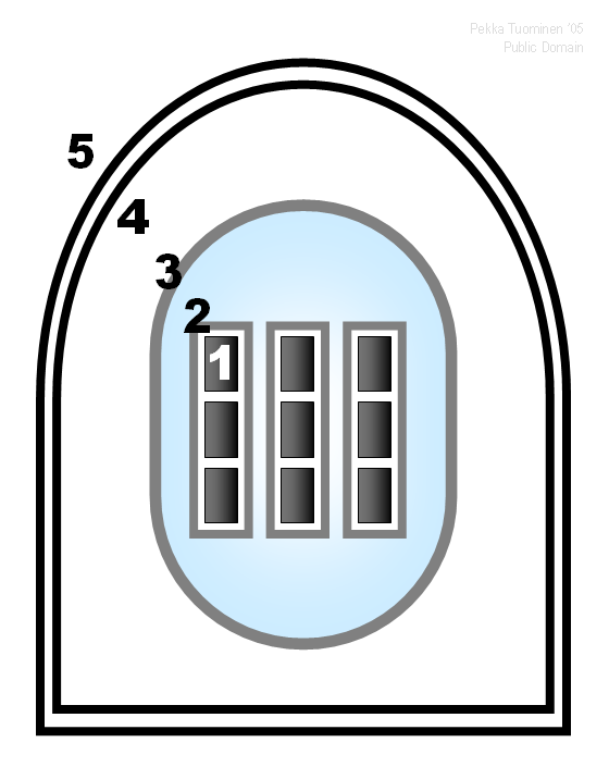
Defense in Depth against the release of radioisotopes required a series of physical barriers that inhibited the movement of radioisotopes from the nuclear fuel pellets, into the environment. In order to illustrate the defense in depth of civilian light water reactors, a brief comparison to the Soviet RBMK reactor is in order. The failure of the safety features of one of the RBMK at Chernobyl lead to the release of large amounts of radioisotopes from the reactor core. The RBMK reactor like Western Light Water Reactors featured ceramic uranium fuel elements made of uranium dioxide baked at high heat. In Western reactors the fuel pellets are clad with Zirconium a sturdy metal that resists the reactors heat and radiation.
The Uranium Oxide fuel is itself the first barrier in the defense in depth, and it is a one of the strongest barriers in the whole defense. Fission products are basically locked in to the rock like fuel pellet. As George Parker and my father were to observe that the release of fission products from Light Water Reactor fuel was cause by a variety of mechanisms that were all triggered by overheating. Thus the first barrier could be breached by reactor over heating.

The Zirconium cladding adds protection against fission product escape. Zirconium has a high melting temperature, although not as high as uranium oxide. Like uranium oxide, zirconium and zirconium alloys are dependent on reactor cooling to prevent to maintain integrity as a barrier to fission product escape. A further consequence of the failure of Zirconium cladding would be that it would subject uranium oxide fuel to mechanisms that promote fission product loss.

A Zirconium tubes in which the fuel pellets rest in the reactor core constitute a third barrier to fission product release, however in practice if reactor core heat is sufficiently high to cause the failure of Zirconium cladding, it will also cause the failure of zirconium tubes. The outer structure of the reactor provides a further barrier to fission product release. In LWRs the pressure vessel is a major barrier to solid fission product release, although radioactive gases can work their way around the barrier in major reactor accidents. The RBMK does not have a pressure vessel, which is perhaps the most significant reason for the massive release of radioisotopes in the Chernobyl accident. The Chernobyl RBMK appears to have included an outer structure designed to maintain the RBMK core in a helium environment in order to prevent graphite burning. This containment structure failed during the Chernobyl incident, and the resulting graphite fire contributed greatly to the fission product release during the Chernobyl incident.

The next barrier to fission product release is the reactor outer radiation shield. Although this shield is seldom mentioned in discussions of defenses in depth, it does provide a barrier to the release of solid and molten fission particles whose movement is limited by the forces of gravity. Thus in the event of a core melt down which penetrated the pressure vessel, the radiation shield would offer considerable containment of the molten fission particles. Because of its massive nature, the radiation barrier would also mitigate a steam explosion powerful enough to rupture the wall of the pressure vessel. The sideways and downward pressure of the steam explosion would be baffled by the massive radiation shield while gravity would contribute to containing the movement of non-gaseous fission products within the outer containment structure. The Chernobyl reactor was surrounded by a radiation containment structure which failed because the of a powerful steam explosion. The cause of the blast was a combination of design flaws that caused a dramatic rise power levels in the reactor when an operator attempted to shut the reactor down.

The destruction of the radiation shield of the Chernobyl reactor removed the last level of containment for that reactor, while another level of containment, represented by the outer containment dome, would have still survived a Chernobyl like explosion. The failure of the Chernobyl radiation shield and the subsequent graphite fire lead the the massive release of radioisotopes from the burning Chernobyl reactor. Thus the critical features that lead to the radioisotope release from the Chernobyl radiation release were not present and two outer barriers to the release of solid radioactive materials, the massive 8" thick steel pressure vessel, and the even more massive outer dome of the reactor were not features of the Chernobyl reactor design. Other unique features of the RBMK reactor design including the use of a graphite moderator, and numerous design flaws that created safety problems contributed to the accident.

Anti-nuclear critics of nuclear safety often point to the Chernobyl accident as evidence of the fundamental safety flaws of all reactors, without noting the significant differences in safety features between RBMK reactors and LWRs. In fact during the Three Mile Island accident the outer safety barriers, the pressure vessel, the radiation shield, and the containment dome all remained in tact. There were no verified cases of radiation related health problems as a result of the Three Mile Island accident, and subsequent research failed to identify any increase in the number of cancer cases that could be associated with the accident. Thus the defense in depth deployed at the Three Mile Island Reactor was successful.

A Note on Radioactive Gases

The radioactive material released as a consequence of the Three Mile Accident were primarily nobel gases. The nobel gases and other radioactive gases are fission bi-products that are present in the uranium oxide fuel pellets, Normally they would remained trapped in the uranium oxide pellets, but if the reactor core heats enough to melt down, the zirconium cladding will rupture or melt, and the melting of the uranium oxide pellets will release the nobel gases. The gases escape from the reactor core through the cooling system. The gases are quickly dispersed by the atmosphere. While nuclear critics rase the issue of radioactive gases as an issue in justifying their opposition to nuclear power, nuclear critics often display a strange inconsistency. Radon, a radioactive gas is also released by coal burning coal fired power plants. In addition natural gas contains radon. More radioactive gas is released into the environment by the use of fossil than by nuclear power plants, yet nuclear critics rarely raise their voices in concern about radioactive gasses released by the use of fossil fuels. In fact, many supposedly pro-environmental, anti-nuclear organizations, accept funds from foundations with ties to fossil fuel produces, sometimes with stipulations that the funds will be used to promote fossil fuel use. Needless to say, these organizations never raise talk about the association of radon gas with fossil fuel use.

I will in a later post discuss a methods of preventing or at least limiting the release of radioactive gases associated with the development of the LFTR.

Thursday, August 14, 2008

MSR/LFTR development: WASH-1222 and Beyond

Where is the LFTR on the product development cycle?

A proof of concept MSR prototype was built in the 1950's. It was regarded as highly successful. A more advanced MSRE prototype was built and tested between 1965 and 1969. It was, like the first prototype, considered an outstanding successes. The MSRE accomplished all experimental objectives The MSRE, tested many advanced technologies, including
* Online reactor refueling
* First reactor to use U-235, U-233, and Pu-239 as nuclear fuel
* The longest reactor runs between shutdowns at the time
* Verified MSR safety features
* Successfully use of the liquid LiF-BeF2-UF4 fuel/coolant formula.
Several developmental problems emerged from the test:
1. Tritium, a radioactive form of hydrogen, was found to have escaped the reactor. This was considered highly undesirable, but not entirely unexpected. ORNL researchers believed that a tritium control system had to be developed. They later accomplished this task.
2. Cracking on the surface of Metal alloys that came in contact with liquid salts was observed. Later research identified the cause of the of the cracking, a fission product, and methods of preventing the problem.
3 Prolonged and heavy neutron radiation exposure of graphite, lead to changes of graphite internal structure. This produced swelling of the graphite moderators which also served as the inner plumbing of the reactor. The swelling of the graphite structure weakened it. This problem has not yet been solved, but it can be worked around. One work around would involve the floating of hundreds of graphite pebbles, that is small graphite balls in and out of the MSR core. The pebbles would not have any structural function, but would serve as a moderator. When the pebbles swell from excessive radiation, they can be captured sas they flote out of the reactor core, and removed from the reactor.

Upon completion of the MSRE, ORNL staff began to design a large (1000 MWe) LFTR, the MSBR. It was designed to serve as a thorium fuel cycle breeder. The jump from the 10MW MSRE to a 3000 MW MSBR was in hindsight overly ambitious, but was necessitated by AEC requirements. The solution to the graphite problem was particularly unsatisfactory. A two fluid core design, that is a core design in which fuel salts and fertile blanket salts were intended to be kept separate, required a graphite core structure. Graphite swelling lead to problems with graphity 2 fluid core structures, and one solution was to periodically remove the core graphite removed and replace it. There are several less drastic alternatives.

Wash-1222 listed a number of developmental issues facing the MSBR design and development team. Wash-1222 stated, "the development of these larger components along with their special handling and maintenance equipment is probably one of the most difficult and costly phases of MSBR development. However, reliable, safe, and maintainable components would need to be developed in order for any reactor system to be a success".

WASH-1222 also noted, "The salt valves for large MSBR's represent another development problem, although the freeze valve concept which was employed successfully in the MSRE could likely be scaled up in size and utilized for many MSBR applications. Mechanical throttling valves would also be needed for the MSBR salt systems, even though no throttling valve was used with the MSRE. Mechanical shutoff valves for salt systems, if required, would have to be developed". This would seem to be a simple developmental task.

WASH-1222 also noted that an integrated fuel reprocessing system would have to be tested, and a design for system integration for the entire MSBR was also required.

Many of the developmental tasks listed by WASH-1222 apply primarily or entirely to the MSBR. Other developmental tasks appeared to be routine and not likely to pose a challenge.

WASH also noted the MSBR "requirement for remote maintenance will significantly affect the ultimate design and performance of the plant system". It then pointed to one of the significant problems with the MSBR design, "the removal and replacement of core internals, such as graphite, might pose difficult maintenance problems because of the high radiation levels involved and the contamination protection which would be required whenever the primary system is opened". This pointed to the most significant problem of the MSBR design, the resolution of the graphite problem by periodic core removal. French MSR researchers, have recently made the choice to follow a developmental track that eliminates graphite from the core of their proposed MSR. There analysis of the difficulties posed by the graphite core of the MSRE, lead them to conclude that despite some significant disadvantages, the a graphite free core offered more advantages.

WASH-1222 raised questions about the safety of the MSBR. Subsequent MSR safety analysis by Uri Gat, and Gat and Dodds, would seem to resolve most safety questions on a conceptual level. Recent discussions in the "Energy from Thorium" raised questions about assurances that the "salt freeze safety valve would operated in a timely fashion in the event of an emergency shut down. My rather brief review of ORNL reports did not shed light on the question. In absence of devinitive evidence from ORNL reports, the proper functioning of the emergency reactor drain system including the freeze valve, should be verified, and any short comings rectified.

Thus the major MSBR developmental problems noted by WASH-1222 were the tritium problem, and the problem of core graphite. The tritium problem requires a technological fix that is clearly not impossible. Several work around ideas have been proposed for the graphite problem, and a French MSR design team has adopted one.

In addition to the developmental issues noted by WASH-1222, the problem of protactinium extraction, a problem that bedeviled my father from the late 1950's to the mid 1960's, has been the subject of continuing discussions on "Energy from Thorium". The tennor of the discussion seems to be as follows, protactinium extraction is difficult and probably should be avoided if possible.

I mentioned alternative approaches to the graphite problem. Again some available options have been discussed on "Energy from Thorium". These include the big pot approach which has attracted french interest. The reactor core is simply a open chamber into which liquid salt coolant/fuel is poured. No moderator is used although the liquid coolant/fuel does have some moderating effect. There are disadvantages to this approach. The amount of fissionable fuel required to sustain a chain reaction would be much greater that in a moderated MSR.

One interesting option would be to put graphite pebbles into the pot in order to provide a moderator. The graphite pebbles would float in the liquid salt and could be periodically removed for replacement. This system was actually suggested at ORNL in 1970.

"Jaro" suggested the use of self-cleansing carbon nanotubes as MSR moderators. Another "jaro" suggestion involved the use of heavy water being piped through the MSR core. There would probably be safety concerns about this design, although heavy water would work even better as a moderator that graphite.

It would appear then that the graphite problem is no deal killer for the MSR. Solutions and work arounds exist for the graphite problem, but reactor developers have to decide which one to choose.

Finally, research on the tritium problem was problem was continued at ORNL into the mid 1970's. Tritium (H-3) is a radioactive isotope of hydrogen that primarily is produced from lithium-6 isotopes. If pure lithium-7 is used in the fuel, then the LFTR tritium problem would be greatly reduced, but not entirely eliminated. Tritium hike the other forms of hydrogen diffuse through metal barriers. Tritium is most likely to escape the MSR/LFTR through the thin walls the heat exchange. ORNL researchers in 1977 later reported that they were making progress toward a solution to the tritium problem when their funding was cut off by the United States government energy bureaucracy. Again the tritium problem seems no deal breaker. The ORNL researchers who were trying to solve the tritium problem stated:
"Although a complete understanding of the behavior of tritium in sodium fluoroborate could not be developed from this series of experiments due to the termination of the Molten-Salt Reactor- Program, the effectiveness of sodium fluoroborate to trap tritium was demonstrated. Furthermore, use of sodium fluoroborate as a secondary coolant in an MSBR would be expected t:o adequately limit the transport of tritium to the reactor steam system and environment".

The ORNL researchers further summarized their findings:

The tritium addition experiments conducted in the CSTF demonstrated sodium fluoroborate’s effectiveness for sequestering tritium. However, further experimentation and research would be required to yield a better understanding of tritium behavior in sodium fluoroborate, to better define
basic parameters, and to explain some of the observed phenomena as a result
of conducting the experiments in the CSTF.

If the MSR program were to be continued, further investigation relating to the following would be desirable:
1. The chemistry of sodium fluoroborate and the trapping process by which tritium is retained by the salt,
2. Permeability values for Hastelloy N.
3. Solubility data for the dissolution of elemental hydrogen (tritium) in sodium fluoroborate.
4. Data on gas-liquid equilibria in the pump bowl in an effort to
explain behavior such as that observed in experiment T4 when, upon increasing the off-gas flow rate to 4 liters/min, equilibrium conditions in the pump bowl between the gas and liquid were altered drastically.
5. Identification of the sink that required saturating before steady state conditions could be established.
6. Determination of the existence of an extraneous source of hydrogen in the off-gas system and its effect (if present) on the behavior and distribution of tritium in the CSTF
".

Thus the obstacles to successful development of the MSR/LFTR mentioned by the WASH-1222, can be. Design choices and promising research avenues known since the 1970's are still available.

Followers

Blog Archive

Some neat videos

Nuclear Advocacy Webring
Ring Owner: Nuclear is Our Future Site: Nuclear is Our Future
Free Site Ring from Bravenet Free Site Ring from Bravenet Free Site Ring from Bravenet Free Site Ring from Bravenet Free Site Ring from Bravenet
Get Your Free Web Ring
by Bravenet.com
Dr. Joe Bonometti speaking on thorium/LFTR technology at Georgia Tech David LeBlanc on LFTR/MSR technology Robert Hargraves on AIM High